
Making a Polaroid Pinhole Camera

I am sure you don’t want to read to the bottom to see the results of not only making a pinhole camera, but using it too. So above is the camera in its finished state, and below is the only photo I have made so far. Read on though, if you are interested in how I went about making this camera, and learning how to use it.
I have been looking at and liking a lot pinhole photographs recently – see for instance this post by ‘schlem’ over at the 52Rolls project for some very high quality shots – schlem provided me with some helpful advice and encouragement that moved me to implement my ideas. This link is to various posts tagged as ‘pinhole’ at 52Rolls and I had fun browsing the many posts from the past few years.
Naturally seeing a lot of pinhole photographs planted an idea that a pinhole camera would be kind of fun to make. But, I did not really want to undertake a huge job, or to mess around with tin cans or oatmeal boxes or other of the simple-modern-classic pinhole camera bodies. Somehow the idea came to me that a Polaroid microscope adapter that came in a free box of camera stuff might work for this. It has no lens, but does have shutter operated by a cable release, bulb setting is the only option. It has a Land 100 film pack attached at the other end of the light tight box, and even has a tripod mount. It seemed ideal, and a very good use for this body which is missing a necessary part for use on a microscope. A bit of research revealed that Polaroid film is a viable option for pinhole photography (other than being really expensive) and that the focal length of this box would have a reasonable angle of view for a Polaroid film size. Also, as I don’t have much spare time right now, this seemed a manageable project since many parts of the project were in place. So, I plunged in, drafting parts of this post as I went along as a way to keep notes, and to avoid a huge blogging job at the end. This worked out well as I made the camera over several days, spending short amounts of time here and there and losing my train of thought more than once.
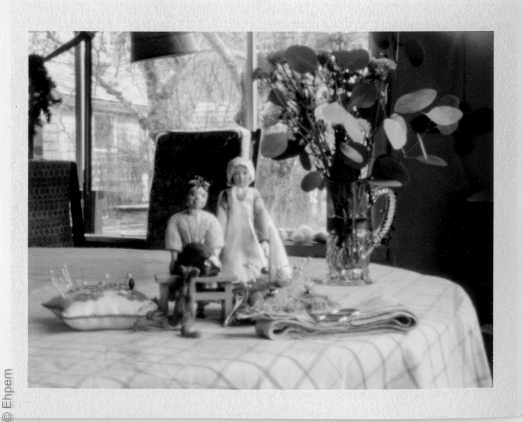
My first ever pinhole photograph – “Still life of Hittys with Pincushions” (what else?)
Open the images in the gallery below to see the original device, an NPC MF-10 Polaroid adapter for microscopy. This link shows all the parts that came with the original setup, some of which are missing from my copy. There is very little information and no decent quality photographs of this camera body on the internet, that I can find anyway. Therefore I have taken a variety of shots and included them here as a contribution to documenting obsolete technology. And so that people might recognise the potential of this equipment if one crosses their path.
Gallery – NPC MF-10 prior to modification. Click on any image to launch larger view and to navigate between photographs.
-

- Unmodified camera, rear view
-

- Side of camera showing cable release attachment. Also, notice the plastic flap extending over the top of the aluminum frame to hide the cut outs for Polaroid land 100 camera attachments, like the viewfinder.
-

- Front of camera, shutter closed at back of the narrower opening
-

- Battery compartment, useful for storing cable release and viewfinder, an exposure chart with reciprocity failure table, or a spare set of car keys!
-

- Back cover open, shutter closed.
-

- Inside of shutter assembly, shutter closed
After studying the camera body and doing rough calculations to see that it was a viable project, I then had to figure out what size to make the pinhole, where to place it, how to mount it, and so on.
The size of the pinhole is determined by the focal length (distance from pinhole to film plane). Fortunately there are some very handy on-line calculators for pinhole cameras. I used MrPinhole, which works like a charm. Using that resource I could determine the ideal pinhole diameter for this body, but first I needed to know where to put the pinhole. I wanted to put it behind the shutter inside the camera body but there is quite a deep well (4 cm in total) in front of the shutter that I was worried might vignette the image. To investigate this problem, it was necessary to calculate the angle of view needed to make the image on this film with the pinhole at this location and to then find the angles of view of the narrower and broader openings in the well (thanks schlem for the suggestions!) Those two cylinders have almost identical angle of view measurements from the shutter, probably deliberately. As this angle is nearly twice as broad as the angle of view necessary to cover the film it is possible to place the pinhole inside the shutter without vignettes. The advantage of this placement is that the pinhole would be protected from physical damage, and from dust and the elements.
Next was to figure out what to use for the pinhole. It looked as if the ideal material would be brass shims. I found that the local modellers hobby shop had a packet of shims ($6) that includes a few small sheets of brass shims with thicknesses of 0.001, 0.002, 0.003 and 0.005 inches. My idea was to make the pinhole with the 0.001″ thickness, and to glue that to a piece of 0.005″ shim for greater rigidity. But how was I going to attach this pinhole sandwich to the camera body? Tape, glue, rare earth magnets? Very small rare earth magnets have their appeal, but on second thought could bind the shutter blades if they too are magnetic. Studying the shutter area I found there are four plastic posts which anchor screws from the outside. These posts are evenly placed and so it seemed like it should be simple to cut the pinhole assembly to fit between them. A square of 5×5 cm makes a nice snug fit, with the protruding corners cut off it would be a tidy fit as well. I made a small template with a bit of foil covered cardboard to test the concept and used it for marking and cutting the brass.
I also had to find something to fit over the posts, such as small nuts, to hold the pinhole assembly in place. That led to rubber (?) tap washers, which when drilled out to 13/16″ are a tight fit over the posts and being rubber were not inclined to slip off. In fact pliers were needed to remove them. I’ve had a half-dozen of those washers sitting around for years, so did not need to buy any. Once I have finished the first pack of film and am satisfied that all is working well I might add something to hold them because I don’t know if variations in temperature or other conditions might allow the washers to loosen – perhaps a small smear of silicon sealer or similar removable material.
Gallery – designing the pinhole assembly. Click on any image to launch larger view and to navigate between photographs.
-

- Inside of shutter assembly, shutter open
-

- Mock-up of pinhole support in place
-

- Pinhole support plate, 0.005″ gauge brass, in place for sizing
-

- Tap washers drilled to size to support pinhole mounting plate, in approximate locations for final placement
With the design in hand I needed to make a pinhole aperture, arguably the trickiest part of the project since precision of the diameter and sphericity affects the clarity of the image. There are all kinds of complicated ways to make pinholes of exact diameter including drilling the hole with a laser (such pinholes can be bought on-line). Other methods include things like making a dimple on one surface and then sanding off the other side very gradually until the hole is the right size. Hole size can be measured with precision instruments, or by scanning at higher resolutions and counting pixels. It occurred to me that insect pins come in very fine diameters and might be a good instrument for making a fairly precise hole. I looked up a supplier on-line and found that a #4 pin is 0.55mm diameter, nearly perfect for my needs (0.574mm ideal size). I know a few entomologists and managed to track down a #4 pin in short order. My partner has a pin-vice which she kindly loaned me and it made a huge difference for holding the pin steadily. For the curious, she has one for her doll carving work and the pinhole picture is of some her doll collection, though neither are made by her; see her doll blog for more information.
The method is settled on uses a pin of nearly the right size and adopts various useful tips from sources like this and this for making accurate pinhole apertures. I cut a 5cm square of the 0.005″ brass shim, drilled in the center a fairly large hole (a giant by pinhole standards), sanded the shim and tidied it up a bit and set it aside. I had a new beer mat in the house and used that to support the 0.001″ shim while drilling. I cut a circa 1cm square of that material for the pinhole – big enough to straddle the hole in the thicker material and also big enough to hold glue well away from the pinhole. I very carefully pierced the shim with the insect pin, keeping it perpendicular to the shim surface. I then sanded the opposite side very carefully with 1500 grit wet and dry sandpaper, making sure to sand in all directions so as not to pull the hole into an ellipse. I put the pin back through after this was done, and then lightly sanded again.
Once this was done I scanned the pinhole at 1200 dpi and counted pixels. I did this twice with the pinhole material rotated 90° as the edges of the hole were hard to discern clearly in the scan. I tried a 2400 dpi scan, but found it did not make a lot of difference to the resolution of the edges and involved twice as much counting with greater risk of getting lost. I found that the hole was very slightly elliptical but I thought close enough. It seemed likely that any attempts to enlarge the hole might exceed the optimum diameter and not be round. The pinhole scan measured as ~27 x ~26.5 pixels, or 0.5714 x 0.5609 mm. The average of 0.56621 mm is optimal for 180 mm focal length, while my installation is 185 mm. I used the average diameter when calculating the f-stop (f-327).
The next step was to glue the pinhole shim to the bracing shim. I marked the thicker shim so as to easily place pinhole near to the center. I wiped the shims with alcohol to help the glue bond and used a two-part epoxy applied to the brass shim carefully around the margins to avoid getting glue near the pinhole. I placed the pinhole square onto the glue surface with tweezers and then slide the pinhole shim on the glue surface until it looked centered, and to ensure a good bond. I then covered the assembly with non-stick silicone coated baking paper and a weight until dry. Once dry I coloured the surface destined to face the film black using a felt pen. It looked like the inner edges of the pinhole were still shiny, so I applied a dab of black to the pinhole from the other side. I also wrote on the remaining shiny surface, in a place not visible when installed, the pinhole diameter and f-stop in case I removed it for storage or replacement in the future. Once dried it was scanned again, and that showed a bit of gunk on one edge of the pinhole, so I ran the pin through the hole again to clear it out. At this point the pinhole assembly was complete and only needed to be installed. However, since that was to be the last step pending other modifications I stored it in a plastic sleeve with the uncut brass shims.
Gallery – making the pinhole. Click on any image to launch larger view and to navigate between photographs.
-

- Pinhole tools – 1500 grit sand paper (background), pin-vice, #4 insect pin, brass shim 0.001″ gauge, beer mat
-

- Pinhole after sanding
-

- Pinhole on brass shim (0.001 gauge) laying out for gluing to mounting plate (0.005 gauge brass shim).
-

- Pinhole glued to mounting plate, front face
-

- Pinhole glued to mounting plate, rear face
-

- Pinhole assembly installed inside camera
The pinhole diameter translates to f-327 with a 35.53 degree angle of view which is equivalent to the view seen through a 42mm lens on a full frame 35mm camera – in other words, near to a ‘normal’ focal length. This was a relief because my initial calculations suggested it was going to behave like a short telephoto lens, which would limit photographic options.
There are only two kinds of film available for the Polaroid Land 100 film pack cameras. There is a colour pack rated at ISO 100 and black and white at ISO 3000. The colour film would require a 4 second exposure (without accounting for reciprocity failure) on a sunny day. The black and white on a sunny day needs to be shot at 1/8th second. The slower film has some serious colour shifting issues at longer exposures (if the specified filters for reciprocity colour corrections are anything to go by), so black and white seems the film of choice. However, with a manually opened and closed shutter, there is no way to expose at 1/8th of a second. The solution is an ND filter, or other dense filter. I have some small diameter ND filters for an Olympus Pen half frame camera which fit every loosely into the front opening. I could not think of an easy way to hold them in there – blue tac might work, but that would be, well, tacky. I also have various 58 mm filters including a variable density ND for my Canon DSLR and thus the idea of a filter mount on the front of the camera made sense. Another advantage of the filter thread is that I can keep a lens cap on the front and thus keep dust out of the pin hole area, even though it is hidden behind the shutter. Dust in the shutter is not a great idea either, so all round a good modification.
I decided the easiest way to hold a filter was to attach a step-up adapter – it looked as if a 46-58 mm ring would fit very well, with the 46 mm part sliding inside the outer tube. I even thought it might be tight enough to self-thread into the plastic for a simple attachment locked with a bit of glue. However, I could not find locally a 46-58 ring. Camera Traders in Market Square (they do internet sales and have lots of excellent used equipment, check them out no matter where you live, you never know but they might have what you are looking for) has all kinds of used step-up rings, and I settled on a 49-58 thinking I could use it with my Takumar lenses if it did not work. It was not right and I was resigned to waiting for delivery of one that would fit. I soon decided, impatiently, to try filing off the 49 mm portion of the step – it was only $8 so not a lot was at risk if I screwed up. I put a filter into the 58mm end to hold it round, making sure to protect the filter with thin ethafoam and painters’ tape over the glass and taped the flat surface of the flange to reduce filing marks. With an axe-file it took quite a while to remove the flange but it worked out well with the filter front remaining round, unmarked and useable.
I attached the filter ring it to the front of the camera with 4 small screws scavenged from an old flash I bought for $2 (I got it for the hot shoe mount when planning viewfinder options). I should have put the screw heads a bit closer to the threaded outer edge so that they stop the filter from going in so far that the glass surface touches the screws. Some of my 58 mm filters have a short distance between the glass and outer rim of the filter and can come in contact with the screw heads. I just need to choose carefully, and in fact this is not the case with my fader ND filter which is the one most likely to be on the front of the camera. Other than that, I think it came out really well, looking as if it is part of the original design.
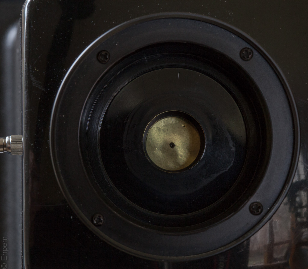
View through front showing filter ring mounted. shutter open, pinhole is within the black area which is a patch of felt pen ink to reduce the shine within the pinhole edges.
The final modification needed was a viewfinder or sighting mechanism for framing shots. I contemplated a film shaped sight on the front, made of wire or something, but it seemed inelegant and likely to be a real hassle. Another possibility was scavenging a viewfinder from a Land camera since that installation should be easy on this camera back that has all the gaps cut into the aluminum frame for a viewfinder hidden under an extension of the plastic body of the camera; though cutting the plastic flap neatly might be tricky. I don’t have a parts Land camera and finding one seemed likely to be a drawn out process. Some of the later plastic Polaroids have a projecting viewfinder that might work, and probably are easily cut off so I could keep an eye open for one; they use a film size no longer available and can be very cheap. Even so, I decided that finding a viewfinder was going to take some time and I needed an interim solution which I decided was to use a film director’s app on my phone and devise a clamp to hold the phone on top of the camera. That was why I bought an old flash with removable locking shoe assembly as I thought I could make a holder that fit on a flash shoe mounted on the camera, and thus be easily removed for storage. While contemplating how to do this, and getting on with other parts of my life, I kept my eye on the local on-line used stuff website. Lo and behold a viewfinder was advertised for $5! Surely this confirmed that the pinhole camera was just meant to happen at this time.
The “Elite” brand viewfinder from the 70’s is marked for 35mm and 50mm focal length lenses on a 35mm film camera. It mounts on a flash shoe. The guy selling it had used it decades ago for sky diving photography; he hung it from his helmet, which had a 35mm spring wound Ricoh mounted on top, and he somehow registered the finder to view what the camera would see and arranged everything with the finder hanging immediately in front of his eye. The wound up spring was good for 6 or 7 shots, so that was what he had per dive. He fired it with a bulb shutter release cord fed through his diving suit with the bulb taped to the palm of his hand. He showed me some photos which were very good shots of the diving team he was on. This view finder even went to the world team skydiving championships in Europe one year. It feels like a bit of a responsibility to use a bit of kit that has such a storied and ingenious history. Now it will be taking slow land based shots; perhaps at this venerable age the finder will appreciate the change of pace.
To install the viewfinder I had to remove the Polaroid film pack unit from the plastic body (four screws only) and attached the flash shoe (which came with it, pre-drilled for the helmet attachment bolt) to the plastic plate on top of the housing. I also had to file a bit off the aluminum under the flap to make room for a nut (I used a brass one that came with the view finder) to hold the shoe. Then, because the plastic is a bit sloping front to back, I added a 0.05″ brass shim to level it a bit – I probably could have added more, but was getting tired of this part of the operation and figured I can learn how to “register” the shot through the view finder with a bit of trial and error. However, I got a 4×5 ground glass from Camera Traders and while it does not quite fit in a film pack opening was still useful for confirming that the framing between the viewfinder and the film location looks close enough to work.
At this point the camera seemed complete and I installed the pinhole. However after installation I found the shutter was a bit sticky and I had to take apart the shutter. I turns out the pin in the shutter release cable was too long and displacing part of the shutter. I put a temporary stop on the cable so it only extends to the point when the shutter is fully open, and reassembled the shutter. It works, but not as reliably as I would like, so I likely will have to take it apart again, and get a different cable release, or perhaps cut off part of the pin that slides into the shutter.
Gallery – completed camera details. Click on any image to launch larger view and to navigate between photographs.
-

- Completed camera, ND fader filter mounted, view finder needs mounting, mounting shoe visible
-

- Completed camera, ND fader filter in place, view finder mounted
-

- View finder mounted, from front, brass shim just visible.
-

- View finder from rear, showing markings for image framing.
-

- Completed pinhole, no filter or lens cap
-

- Completed pinhole, lens cap in place
-

- Adhesive backed foam added after outdoor testing of camera to eliminate glare from shiny tube in front of pinhole.
Now that the camera was ready to go, how to use it? I had bought two packs of Fuji FP-3000B and was anticipating complicated calculations for exposure determination with an f-327 camera. Once again MrPinhole came to the rescue, this time with a light meter guide for pinhole users. My spotmeter can be set up to f128, so using the conversion chart I find that for ISO100 film, I can set my light meter to f128 and ISO16 to get the correct length of exposure. Likewise for ISO3000 film, I can set the meter to f128 and ISO500 to calculate the exposure time. That solves one problem very easily; I just have to meter the scene correctly which is not something I am all that good at. I metered this scene from the highlights, and compared it to the matrix metering of my Canon DSLR – they came within 1/2 stop of each other, so that was reassuring.
I looked up the reciprocity failure information for the two kinds of film involved, and wrote them down. Eventually I will stow a copy in the battery compartment.
When I got my Cameron Fader ND filter a few years ago I marked approximate f-stop changes on the ring. These I compared to the incident light meter reading on the spot meter (with the bulb recessed for copy mode) and found them to be quite different from what I saw through the camera. I am not sure what this means, but have made notes about it and will probably have to test it a bit to find the right exposure values. Ideally I would get a fixed ND filter without complications, but for now this is all I have so will live with it. I am going to check it again against the camera and light meter in case something has changed with the filter, or reading it under artificial light is the cause.
No other tasks remained prior to taking pictures, so I set up a scene indoors as a first test, and at the time of writing, the only test. I think that this first shot, which took into account just less than 1 stop of reciprocity failure, and was metered for the highlights on the doll dress, is over exposed, perhaps by 1 stop – the greyness of the white edges of the print are a giveaway, but I was trying to deal with the highlights when scanning. I metered it at 8 seconds, but shot at 14 seconds, just a bit less than 1 extra stop for the reciprocity adjustment. Whether this result indicates the pinhole f-stop measurement/calculation is a bit off, or the sensitivity of the film is less compromised by the long exposure than suggested, I don’t know. I suspect that with time I will find how best to shoot it in different conditions, but sure would appreciate any shared experience of this film, if anyone is using it for pinhole photography.
After testing the camera out of doors, and after first publishing this post, I found that there was a lot of flare on the images that appeared to originate mostly from the shiny surface inside the tube in front of the pinhole. Some also originates from the fader ND filter, quite how is not yet clear to me. I added some self-adhesive black craft store foam to the interior surfaces of the larger diameter tube behind the filter mount. This has eliminated most of the flare on the subsequent images. I have added a photograph of this slightly messy mod in the gallery above – I could not find something that would cut a neat circle of this size. Likely I will replace the bottom disc with a neater job, though this one does the job.
I scanned the print and also the negative image on the other piece of paper. This film is not constructed to allow recovery of a transparent negative the way the FP 100B is. But the negative on paper can be useful, especially if you give the print away before scanning it. There is a bit more information in the shadows on the negative, though my scanning method has exaggerated the difference. Included in the gallery below is also a DSLR shot of the same scene, made with a 50mm lens at f22 and ISO3200 for comparison. The image is not as sharp as it could be for a pinhole camera and that is probably due to the slightly oval pinhole with a suboptimal diameter. But, it is sharp enough for my purposes and probably will work well with longer views.
One bonus in all of this is that it turns out the inner rectangle in the viewfinder is almost exactly right for this film, even though it is supposed to be for a wider angle. Perhaps that is something to do with the distance from the pinhole to viewfinder or some other physics of light explanation that I don’t get. Or maybe, again, my pinhole measurements are a bit off. Whatever the reason, I’ll take it.
Overall, this was a highly satisfying project. The price was right – just over $20. It only took a few hours, spread over more than a week, and with casual thinking and planning time (read ‘dreaming’) for a few months before that. To re-purpose this gear to a functioning state is really nice. I can hardly wait to get out and take a few shots of water and other things. It should be a lot of fun. I must remember to keep that filter clean when using it, dirt specks could be in focus!
Gallery – taking the picture, and the results. Click on any image to launch larger view and to navigate between photographs.
-

- Close up of camera back, on tripod
-

- Looking over camera at first image set up
-

- Timing development of first image.
-

- Polaroid print
-

- 1. Edits in LR5, not as good as print
-

- View of the set for the first shot, made with a 50mm lens at f22.
Digital photos taken with Canon 5Dii and Canon 50/14, 100/2.8 macro and 16-35/2.8 lenses. Positive and negative pinhole photograph scanned with Epson V700 and processed in Lightroom. Scans of the pinhole made with a HP Photosmart 7520.


Pingback: Pinhole Graffitti | burnt embers
Pingback: Expired Film Day pt. 1 | burnt embers
Pingback: Worldwide Pinhole Day 2017 | burnt embers
Pingback: Pinhole with Canon EOS3 | 52 rolls
Pingback: Instant Film for Worldwide Pinhole Day | 52 rolls
Pingback: Gonzales Pinholes | burnt embers
Pingback: Polaroid for Worldwide Pinhole Day | 52 rolls
Pingback: Pinhole Polaroid Negatives | burnt embers
Pingback: Testing A Polaroid Pinhole Camera | 52 rolls
Oh wow. This is dedication with a creative spin. Congrats on making it work and I hope that this will be useful for more than 2 people out there 🙂
LikeLike
Thanks Angelina. That would be nice but I don’t think there are many of these polaroid bodies out there.
LikeLiked by 1 person
so interesting!
LikeLike
Thank you Souhade. Glad to hear that from someone so much into pinhole photography.
LikeLiked by 1 person
I wish I could change a polaroid camera into a pinhole camera…
LikeLike
This one was pretty straightforward. I would think that any of the Land cameras could have their lens taken out and replaced with a pinhole – there must be lots out there with broken shutters or glass. The way they are arranged it might even be possible to install different pinholes and rotate one into place for different focal lengths. I have a Land 100, but it is working and I don’t want to wreck it!
LikeLiked by 1 person
I’ve come from the QHitty blog to get further insight into what you’ve done. I do not understand any of what you’ve created, BUT, I do know that you have used your creativity, knowledge and inventiveness with what you have in front of you as well as what you sought out, and you’ve made a wondrous camera out of it all. Cheers to the gift and spirit of creativity that you took hold of and what came of it. I thank you for sharing.
LikeLike
Hi Becky – nice to see you here, I have often noticed your comments on the QuimperHitty blog. Thanks for you kind words – I suspect this post will be of detailed interest to only about 2 people in the whole world, if they cand find their way here. But it was fun to document the process of making a camera from parts.
You won’t find too many Hittys here, but there are some. If you check this link you can find all the posts with Hittys (unless I forgot to tag some).
LikeLike
Pingback: Pins and Needles | Quimper Hittys